V0.4 May 30, 2014
Often times it is necessary to shift a variable voltage source to another. This is often needed for sensors such as transducers, encoders, pressure sensors, temperature sensors, analog sources, etc.
This page will show how to convert any variable level source into another span of levels. I will provide a number of real problems below and how to solve them.
In these examples a power supply of + 15 and - 15 volts will be used. Lower voltages can be used if the source voltage and desired output voltages aren't exceeded. General purpose opamps are LM1458, 4558, NE5534, or equivalent. In these demonstrations no filtering and bypassing is shown. Resistor values shown are not necessarily available off-the-shelf. It may be necessary to "series" two resistors to get the values required. A digital multimeter set to ohms scale can be used to hand pick values for the desired results.
First some basic understanding:
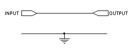
If the input reflects exactly what the output is then you have a straight thru circuit as shown below.

What is applied to the input appears exactly on the output. No real magic here. But if the source of the signal is a somewhat higher impedance and the load is larger, a unity gain amplifier or source follower is required.
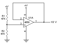
Using a unity gain op amp you can achieve the desired results the same as the above circuit by using the following:

What is applied to the input will appear exactly on the output with the exception of a higher drive level. Sometimes digitally referred to a high fanout.
From the Understanding op-amp page, it states that the + input is a very high input impedance meaning it will not load your incoming source. Also the output impedance is very low, typically 47 ohms or less depending on device. In the circuit above, R1 can be almost any value from 100 ohms to 470,000 ohms with no adverse results. It can even be eliminated in some circuits.
In the circuit below a voltage divider and follower is used to provide a high level bias point in a single supply audio circuit..
To level shift a 0 to 10 volt source to 0 to 5 volts, the circuit below will provide this:
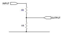
Any pair of equal resistor values can be used. Typically 10K to 100K. The higher the resistance pair, the less of a load you will impose on the circuit. The caveat is that the output load cannot be great enough to load down the voltage divider. If it is, the output voltage will be lower than desired. A follower or driver can have a high impedance input and a low impedance source. The circuit below is an example:
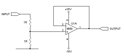
The above divider resistors 1R in two places could be as high a 1 meg ohm as long as they are precision type or properly matched.
With the above circuit the following outputs can be achieved:
|
Input |
Output |
| -10 | -5 |
| -6 | -3 |
| -3 | -1.5 |
| -.5 | -.25 |
| 0 | 0 |
| .5 | .25 |
| 1 | .5 |
| 4 | 2 |
| 12 | 6 |
Since this is a linear analog amplifier, any voltage, positive or negative will be exactly one half on the output.
Another example is a piece of equipment that provides a signal from 0 to +.1 volts and the remote metering circuit is looking for a 0 to +10 volt signal. Use the formula Vg=Vout/Vin or 10/.1.
A gain circuit will convert 0 to 0.1 volts to 0 to 10 volts. The circuit below has a voltage gain of 100.
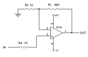
Circuit 003
In the circuit above what ever voltage appears on the input will be one hundred times in magnitude on the output.
|
Input |
Output |
| -0.2 | ~ -13* |
| -0.1 | -10 |
| -0.06 | -6 |
| -0.05 | -5 |
| 0 | 0 |
| 0.033 | 3.3 |
| 0.05 | 5 |
| 0.08 | 8 |
| 0.2 | ~13* |
*Note the first and last entry in the table the output should be 20 volts. Since the power supplies are + and - 15 volts, the opamp output reached the limit of the parameters of the opamp which is about a volt and a half or less than the 15 volt power supply rails. There are newer opamps that are considered rail-to-rail which means the output comes close to the actual power supply rails, typically around a quarter volt from the rail.
Example A. A piece of equipment provides a range of 0 to 2 volts and you need a telemetry input of 0 to 10 volts to show a full scale reading. Since 10 over 2 is 5, then the voltage gain will be 5. Use Circuit 003 and change R3 to 4K.
To calculate the resistor values for other opamp gain use the following link. OPAMP CALCULATOR
If you need to offset the output of Circuit 003 so instead of zero volts out with zero volts in, you wanted -2 volts out for zero volts in. The results are in the table below.
|
Input |
Output |
| -0.2 | ~ -13* |
| -0.1 | -12 |
| -0.06 | -8 |
| -0.05 | -7 |
| 0 | -2 |
| 0.033 | 1.3 |
| 0.05 | 3 |
| 0.08 | 6 |
| 0.2 | ~13* |
Use the circuit below adjust the pot for -2 volts out when the input is at zero:
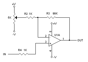
Circuit 004
With the circuit above the variable resistor is used to offset the output over its entire range. But there's a problem. The gain of 100 is determined by the left side of R2 going to ground or a very low impedance. But the wiper on the 5K pot that varies the offset never sees ground or a low impedance ground such as the power supply rails unless the wiper is at either end of its range. Even though the offset will function, the gain will decrease to 30 with the pot set to zero volts. This is because the 5K pot set to center is actually 2.5K to each rail. The rails are considered "ground" as far as the gain is concerned. The left side of R2 must see a ground or virtual ground (or low impedance) in order to achieve a consistent gain of 100 throughout its range. The following circuit will provide the virtual ground and a way to still adjust the offset voltage.
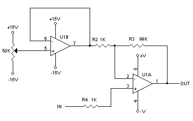
Circuit 005
In the above circuit the input of R2 sees a virtual ground from the output of U1B since opamp outputs are typically a very low impedance and the pot connected to the follower circuit of U1B provides the offset required.
I will now show how to interface to an analog meter display. To understand how to calculate meter resistors, study the Meter Multiplier page.
In Example A above, the equipment is providing a 0 to 2 volt output. The telemetry monitoring circuit requires a 0 to 10 volt swing for a full scale reading. An analog meter will show a full scale reading when the equipment is sourcing 2 volts for a full scale reading. Use the following circuit below.
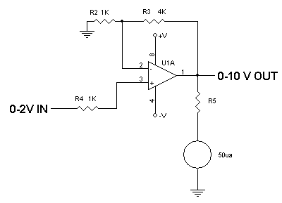
Circuit 006
Since there is a 0 to 10 volt amplified source, that voltage source will give the results desired. In this example the meter internal resistance is 2700 ohms. The total current (Rt) through the R5 and the meter is 50 microamps or 0.00005 amps. Using the formula Rt=E/I, 10/.00005 =200,000 ohms. Subtract the internal meter resistance of 2700 and you will need a resistance of 197,300 ohms for R5.
In the real world it will be hard to find resistor values with the results shown. It may be necessary to series or parallel some values to get the desired resistance. The EIA table shown below are of common resistor values that can be used. Try to use 1/4 watt 1% precision film resistors in all these circuits shown.
|
EIA Standard Values E96 series: (1% tolerance) These values are the most significant digits. Multiply by .01, .1, 10, 100 to get available values from vendors or distributors. |
Example: From the above table if you desire a 197,300 ohm resistance, a 187,000 ohm and a 10,200 ohm resistor in series comes to 197,200 ohms. Since 1% of 197,300 is 199,273 to 195,327, the 197,200 ohm series network is well within tolerance.
If more accuracy is required, round off the 197,300 to 200,000. Take ten percent of 200,000 which is 20K and use this as a pot value. Take half the value of the pot which is 10K and subtract it from 197,300 which is 187,300. A 187K resistor and the 20K pot will sweep through the desired range (187K to 207K) to accurately calibrate the meter to 10 volts full scale.
Meter scales may not display your desired range. There are CAD programs that will output overlays for your meter faces such as Tonnesoftware.com.
Next I will show how to add a relay or indicator light to activate when a voltage reaches a preset value. This could be used for an alarm trip indicator.
There are many devices and comparator chips out there that can be used but learning how to use a standard opamp is useful. I will be using the same opamp device to keep part differences to a minimum. The first section shown below is the same as Circuit 006. Another opamp is shown as a comparator with a vmos fet driver. The opamp has no feedback so the opamp U1B is considered running in an open loop condition (infinite gain) which means the output will be at either the negative or positive rail. When the non-inverting pin 5 rises just above the voltage set on the inverting pin 6 reference point, the opamp output will swing from the negative rail to the positive rail. Q1 will saturate and light the led. As soon as pin 5 drops just below the pin 6 reference voltage the output will swing all the way negative and the LED will extinguish.
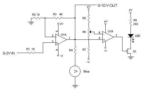
R5, 6, and 7 should be selected to set the trigger point. The smaller R6 is, the more accurate your trip point is except the range will be smaller. A 20 turn trim pot would give a larger range with better accuracy.
Example B.
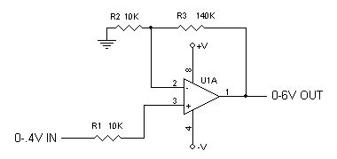
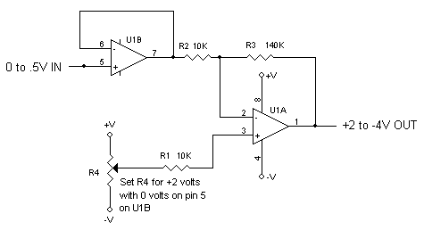
A pressure sensor that varies from 0 to 0.4 volts and the display or other readout needs to show a span of 0 to 6 volts. I will then show how you can also make it show an output of +2 to -4 volts with a 0 to 0.5 volt input.
Vg= Vout / Vin=6/.4=15
xxx
Terminology
Rail - power supply source or buss
Pot - potentiometer, variable resistor
Wiper - adjustable tap on a variable resistor
Follower (or driver) - amplifying device with only unity gain
Window comparator -