Often times you will need to make meters read other than what it normally indicates. These instructions are primarily for analog (mechanical) meters but it also applies to digital display meters.
Most sensitive meter movements are very low current type. Typically 50 microamps and sometimes 20 microamps to 1 milliamp or more for a full scale reading. Even others may display actual full scale voltages. These typically have an internal multiplier resistor contained in the body of the meter.
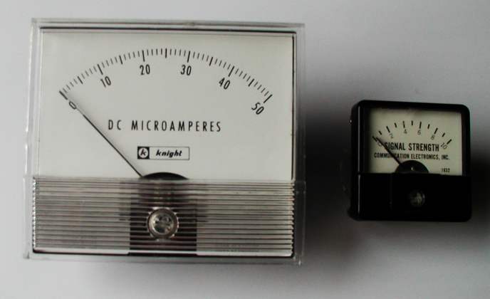
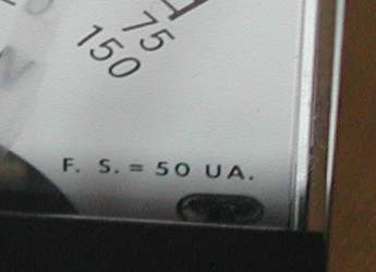
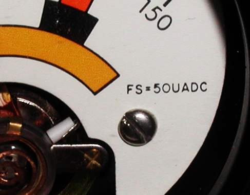
Many meters often display the actual full scale current of the meter coil usually in the lower right of the display face.
There are two basic configurations of meters. Current and voltage type, and other secondary function types such as AC reading, VU, peak reading, or iron vane type. A typical 50 microamp meter can be configured to read either voltage or current. The only other thing you have to do is change the type (numbers) on the meter face. Software is available to make your own meter face from Tonnesoftware.com.
Current meters usually have a resistor across the meter coil (in parallel with the meter) which is called a shunt as seen below.
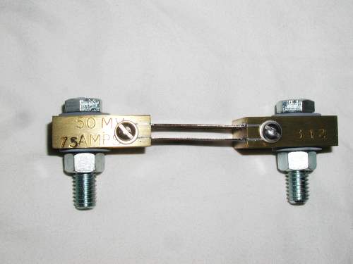
High current shunt meters may have an external shunt with terminals to connect to the meter. The shunt usually has markings on the device itself stating what voltage will be created to achieve a full scale reading. As an example it may say 50 millivolts for 75 amps. This means if 75 amps of current travels through the shunt terminals, there will be 50 millivolts measured across the meter terminals. Example below.
Go to Section 2 to calculate shunt resistors for measuring current.
Section 1 Voltmeters
Volt meters have a precision resistor in series with the meter coil sometimes known as a multiplier (R) as seen below.
Before selecting the appropriate multiplier resistor, it is important to know what the internal resistance of the meter coil is. A typical 50 microamp meter could have and internal resistance of about 600 to 3000 ohms depending upon the manufacturer. If you don't know the internal resistance there are a couple methods to determine this. It is not recommended to just use an ohm meter to measure the resistance because you may do physical damage the movement if the measuring current of the ohmmeter exceeds the meter movement current.
Method #1
A variable power supply, a precision resistor of about 100k ohms (90.9k is typical), an accurate digital multimeter, and the unknown meter movement. Connect together as shown below.
Verify the 90.900 ohm 1% resistor with an ohmmeter so as not to damage the movement. With the power supply energized, start from zero volts and increase the voltage till the meter reads full scale. If at any time the meter pegs, immediately remove power and determine the problem.
Once a full scale reading is observed, measure the voltage across the power supply and write it down. Given a meter of 50 microamps full scale, use Ohm's Law to calculate the internal meter movement resistance.
Since it is a series circuit, the current through the total circuit is 50 microamps or 0.00005 amps and is represented by the letter "I". If the noted voltage taken was 4.68 volts, this will be represented by the letter "E".
Calculate the total resistance using:
R=E/I
So the total resistance is the voltage over the current. Divide the voltage E by the current I
4.68/.00005
The result is 93,600 ohms. Subtract the known resistor value of 90,900 ohms to get 2700 ohms. This will be the actual internal resistance of the meter movement.
Method #2
This will also require an accurate digital multimeter, a 9 volt battery, a 100k pot (potentiometer) and a 100 k resistor for protection. Measure the exact voltage of the battery. Example: 9.26 volts. This will be the "E" in the formula. Insure the pot is at its maximum resistance by rotating it to one side and measuring it. Hook up the circuit as shown below. Connect the battery. There may be an initial indication on the meter. Rotate the pot slowly until the meter reaches full scale. Carefully remove power and measure the total resistance of the pot and fixed resistor without jarring the pot shaft. Note the resistance.
With the voltage "E" (9.26) and the total current "I" (.00005 amps), use Ohm's Law to calculate the total resistance:
R=E/I
9.26/.00005 will result in a total series resistance of 185,200 ohms.
Subtract the resistance 182,500 from the calculated total resistance of 185,200 and you will get 2700 ohms which will be the internal resistance of the meter movement.
Section 2 Ammeters
In this example the 50 microamp meter movement with a 2700 ohm internal resistance will be used. If a shunt is needed to make the meter read 5 milliamps full scale, first determine the voltage for a full scale reading. Since 50 microamps is 0.00005 amps and the resistance is 2700 ohms, use Ohm's Law to calculate the full scale voltage.
E=IR
or, E=(0.00005 * 2700) or 0.135 volts.
So R1 below must develop 0.135 volts across it for the meter to read full scale 5 milliamps.
Ohm's Law will be used again to calculate the resistance.
R=E/I
or R=(0.135/0.005) or 27 ohms. Since the internal resistance of the meter is high, it won't be necessary to add it to the formula. However the tolerance of the 27 ohm shunt resistor may affect the accuracy so increase R1 slightly and use a variable resistor in series with the meter to calibrate it as shown below.
If a meter reading of 1 amp full scale is desired, the formula R=(0.135/1) or 0.135 ohms. Again, exact resistances that small are not available so a pot in series will trim the readings for better accuracy.
New! If you would like to use an XL spreadsheet to calculate meter resistors click here.
If you would like to design a new meter faceplate, there is software to do this from Tonnesoftware.com.