An SWR (Standing Wave Ratio) meter is an instrument used to measure the amount of reflected power (power coming back from the antenna and/or transmission cable) to the transmitter. For a transmitter to provide all the power to an antenna, the antenna needs to be resonant and the transmission cable (coax) has to introduce minimum loss. In a perfect scenario, in an efficient antenna system, all the power outputted from the transmitter makes it into the atmosphere. Both the coax and the antenna, if not tuned right will induce losses. These losses will not make it out to the air but come back to the transmitter in the form of "standing waves".
SWR is the ratio of the forward power vs the reflected power. A perfect antenna system will show 100% forward power and 0% reflected power and is referred to as 1.0:1 which is hard to maintain. Typically a 1.1:1 is ideal and 1.2:1 is average. Anything over 1.5:1 is suspect and needs troubleshooting or tuning. 2:1 is unacceptable and could damage the transmitter if it doesn't have reflected power protection (foldback) circuitry. A 1.0:1 is 100% efficiency to the atmosphere. A 1.1:1 is 0.2366% loss, a 1.2:1 is 0.826% loss, a 1.5:1 is 4% loss, and a 2:1 is 11.1% loss of power. A more detailed table can be seen here.
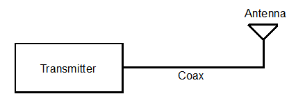
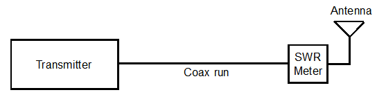
An SWR meter is a device that can be purchased or built by the user. The price for an SWR meter can be anywhere from $35 to over $600 depending on the highest frequency and accuracy it can be used for. Cheaper ones can be used for CB, 27mhz down to the lower HF ham bands, 3.5 mhz. Below is a typical hookup of the antenna system.
Typically, an SWR meter is placed between the transmitter and the antenna usually at he output of the transmitter as shown below.
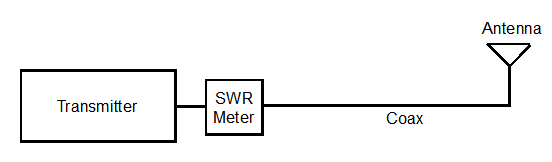
Unfortunately you cannot tell if a problem is in the antenna or coax (transmission line) if it is placed at the output of the transmitter shown above. Placing the SWR meter at the output of the transmitter may not necessarily show accurate reflected power since losses in the coax can show up as a decrease in reflected power. Also if there is high SWR, it can show a high false reading of output power from the transmitter.
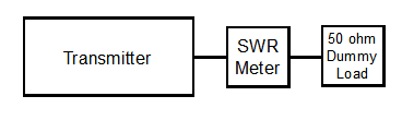
To accurately measure output power of transmitter you must place the SWR meter between a good 50 ohm purely resistive "dummy" load and the transmitter as shown below. Accurately note the power out first. Be aware that some SWR meters cannot accurately measure power output. Just relative output for indicating reflected power.
The SWR meter should then be placed between the end of the coax run with a dummy load as shown below.
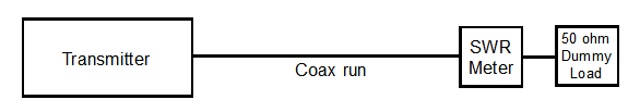
The difference in the power first noted and this second reading will determine the "insertion loss" the coax induces to the circuit. This loss can be measured in watts, or if calculated, by the length known good coax and the frequency in dB. Example: 100 feet of RG-8 coax at 145 mhz calculates to -2.7dB loss or 57.7% efficiency. A good online cable calculator can be found here.
To check the antenna resonance, performance, or to tune it, the SWR meter should be placed between the coax run and the antenna as shown below.
A word about SWR meters. Make sure you know how to use it. Typical cheaper units have a calibrate knob that you set to full scale or calibration point when transmitting, then flip a switch to read reflected power. These sometimes don't actually measure power output accurately unless it has a switch to read direct power.
It is important to note that another way to measure the performance of the antenna and coax without a transmitter is an "antenna analyzer". The advantage is that you don't need a transmitter to determine the effectiveness of the antenna and coax thus not causing interference up and down the band. It may also show the impedance and resonance along with the usable frequency range (bandwidth) of your antenna. You can "tune" the antenna by lengthening or shortening its main radial.
One example is the MFJ-259D antenna analyzer.
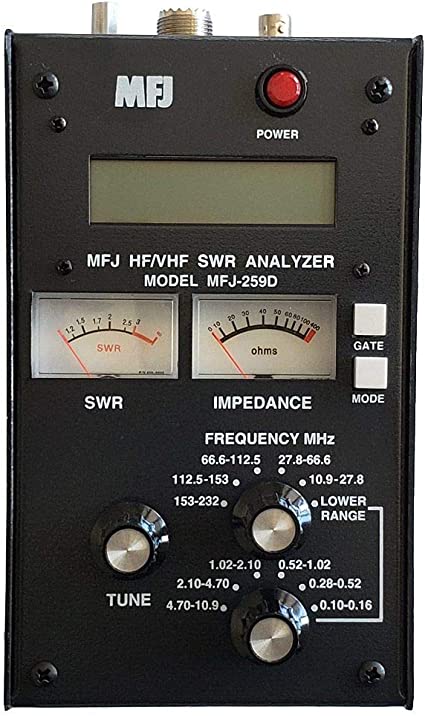
Every ham should have this analyzer for experimenting.
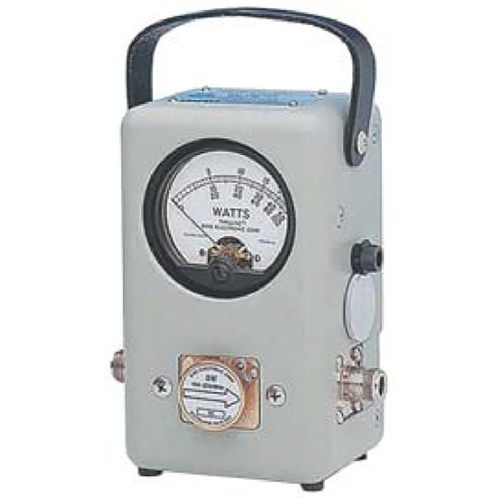
The industry standard is the Bird 43
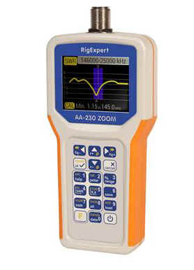
There are more modern analyzers with a digital graphics display such as the Rigexpert.
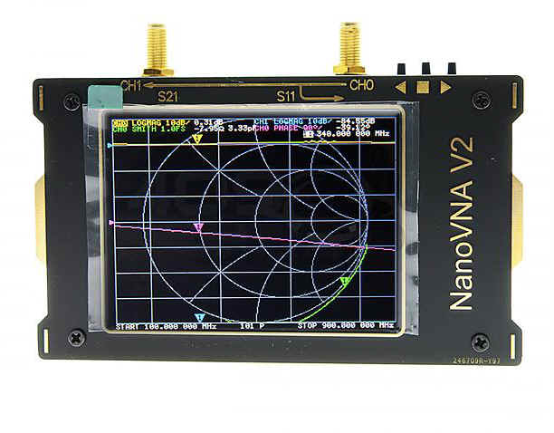
VNA's are highly sophisticated but tell a more detailed story of your antenna system.
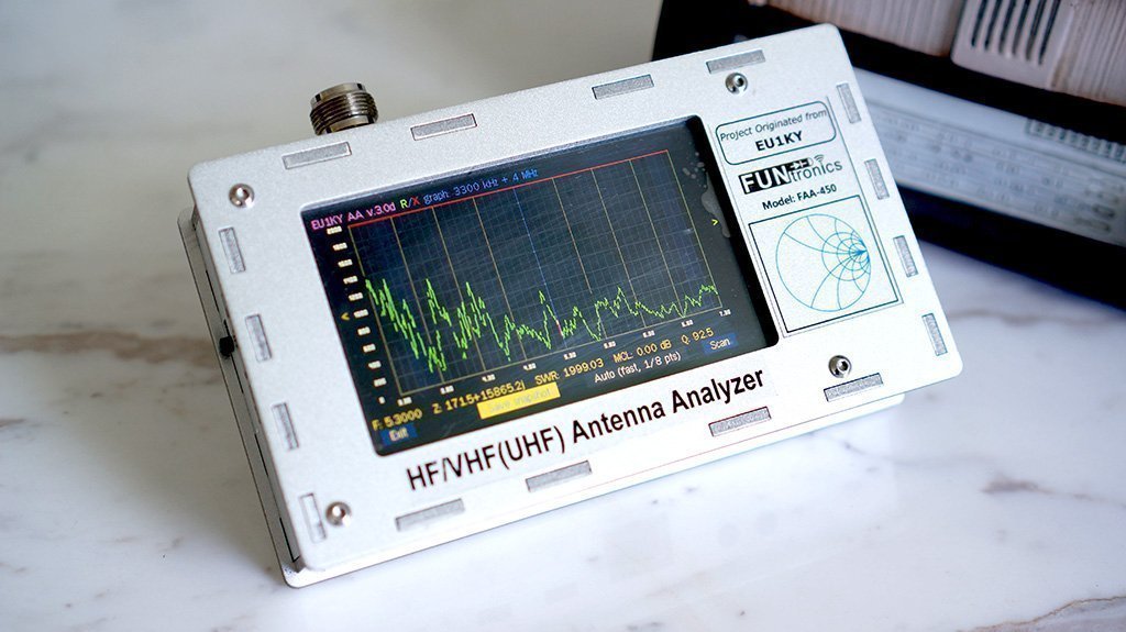
Another newcomer to the field is the Funtronics FAA-450. It is simple to use and can perform many analysis of your antenna system without a lot of fidgeting around with setup options.
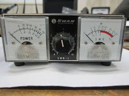
There are a number of low cost SWR meters but remember, the cheaper the units, the less higher frequency range it will perform at. In other words, they will not work into the VHF range unless specified. Also there are active and passive SWR meters. Active meters usually have a digital display but not always. They require battery power. Passive SWR meters don't require any power and will register or display the readings continuously. An example of passive meters are shown below.
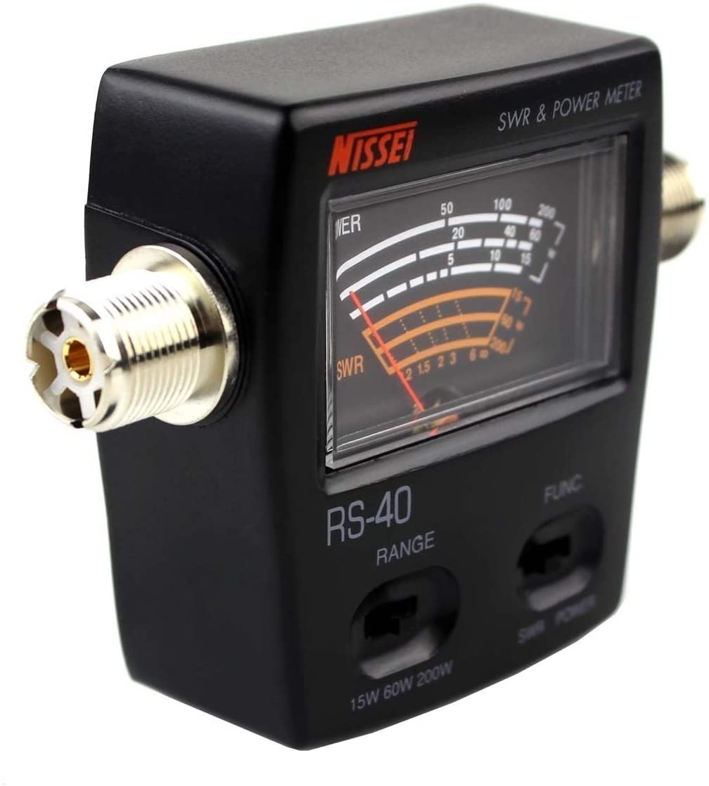
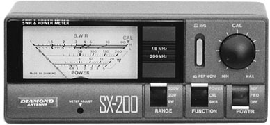
The above meters work basically the same way. They may have a "Power" and "SWR" setting. In the "Power" setting the meter will display power in watts. In the SWR mode, you key the transmitter, set the needle to a calibration point, then flip a switch to read "Reverse" power. An ideal antenna and transmission line will show no power in the "Reflect" mode.
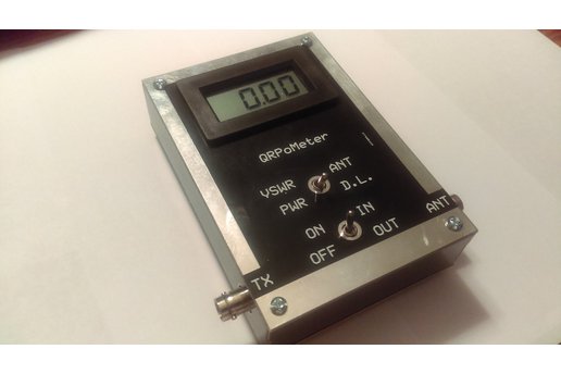
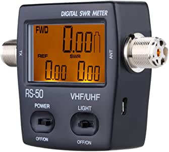
Digital meters like the QRPO Meter and the RS-50 will show exact numbers but show unstable readings if power fluctuates. These meters are shown below.
You can make your own homebrew SWR meter from plans in the ARRL handbook too.
If you question the quality and integrity of the transmission line you can use a TDR. (Time Domain Reflectometer) This will graphically detect where a break, splice, or damaged section is and how far down the coax the problem is.
This page Copyright ©2021 Rick C. Feb 15, 2021 Ver 0.21