Figure 1
V1.1 Original document created November 25, 2003 (c)2003 Rick C.
Plated thru holes are used to electrically connect the pad or trace on one side of the board to a pad or trace on the other. Plated thru holes are easily created during the process of making printed circuit boards by circuit board fabricators. It is not easily accomplished by the hobbyist or engineering prototyper. Too many chemicals and processes make the task difficult and expensive.
For small runs, eyelets can be used to accomplish a thru hole connection. But these too, are also costly and very unreliable. An associate of mine was told to investigate why there were failures on a product with a circuit board. He found that there's a big problem with eyelets in areas where there is any chance of stress created due to heating and cooling or flexing of the board or parts connected with eyelets. The end result of this is a cracked solder joint. It has to do partially with the TCE differentials that are created across the solder connection. Also there is a good chance that when the eyelet is crimped onto the circuit board the annular ring or land area is compromised due to compression and/or scoring of the copper material. He did some fairly exhaustive research on the subject after which they discontinued the use of eyelet's entirely due to the type of failures. Since then he has never used an eyelet in a PCB design and the problems disappeared.
Design of the board must be taken into consideration. First, layout of the board is important. The boards must have most of the traces on the bottom layer. Any traces that cannot be completed will go on the top side. If I have the option of making a connection on the top layer to a dip package or a discrete component, I will choose the latter. Then, most of the thru hole connections can be accomplished by soldering the component pad on the top layer, accomplishing the thru-connection. However, there are some connections that one cannot reach with the soldering iron on the top layer such as dip sockets, relays, terminal strips, headers, etc.
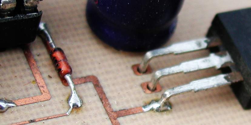
Discrete components such as resistors, capacitors, and diodes have exposed leads can be soldered on both sides of the board, thus completing the connection from the bottom to the top as shown in Figure 1.
Figure 1
If not, the following is my method:
A process I use has been very effective and economical. It takes only about 20 seconds to complete each connection. I start by making most of these connections before inserting all the components on the board.
The only additional item you will need is #30 Kynar wire wrap wire. This can be purchased from many parts suppliers such as Jameco, DigiKey, Hosfelt, MP Jones, etc. A single spool of wire will last a lifetime of double-sided board prototypes.
Start by identifying the pads or via's that will need the connections. Figure 2 shows which pads on the top side that will need the connections.
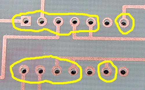
Figure 2
Strip an inch or two of wire from the spool. It is wasteful and not necessary to cut a piece off the spool. From the bottom side, thread the end of the wire into the hole that needs the thru-connection only about 1/8 inch (~4mm). Fold the wire down against the top pad as in Figure 3,
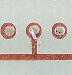
Figure 3
and lay the board flat on the workbench as in Figure 4 bottom side.
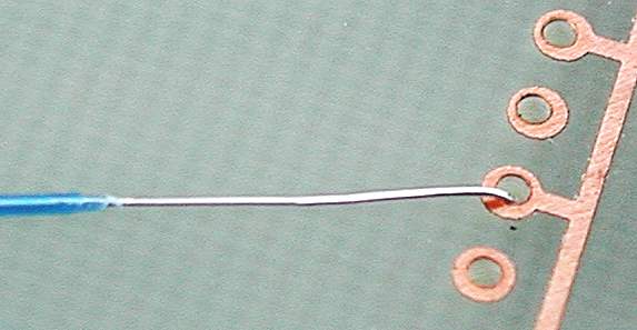
Figure 4
With a small point soldering iron, tack a very small "blob" of solder on the wire to the top pad as in Figure 5.

Figure 5
This "blob" should be very low in profile. Use sufficient heat to flow the small "blob" to the pad. Turnover the board and pull the wire gently and cut the wire off at a length no longer or shorter than the size of the bottom layer pad. Tack another "blob" to the bottom pad to complete the connection. This will also look like the connection in Figure 5. This can be done to either a component pad or a via. Trim the excess wire on the top and bottom of the board so it does not extend beyond the pad diameter. If using an Xacto blade, be careful not to cut the trace in half. Sometimes it is not necessary to solder the bottom connection until you have installed the components and are ready to solder the bottom of the board. All dip sockets will easily fit into the hole along with the wire. Most PC mount relays and headers are square and will easily fit into the hole along with the wire. Figure 6 shows a dip socket with two successful thru hole connections.
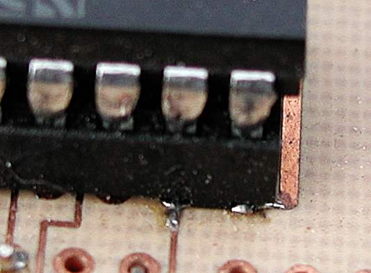
Figure 6
Wire wrap wire can come in a spool dispenser as shown from OK tools as shown in Figure 7.
Figure 7
Any questions or comments may be directed to Rick.
Back to "Making Excellent Printed Circuit Boards"