This may sound too simple for those of us that have used LED's for years, but there are those (especially software guru's) that haven't built their first project yet. Simply, an LED is a Light Emitting Diode. When it is forward biased, and a current of about 10 milliamps is reached, the diode emits visible light (although some special LED's emit infrared or ultra violet light). Forward biased means that a positive voltage applied to the anode and a negative voltage applied to the cathode will cause the diode to conduct. See theory. When this happens, photons will be emitted from the "P" substrate. Some LED's are diffused meaning the plastic case is "cloudy" and the light is spread out evenly from the surface. A clear LED has a clear plastic package and the light is more of a pinpoint. It also has a tendency to beam the light at a distance away. Clear LED's cannot be seen as good from off of the side. A typical LED is shown below.

Usually there is a flat edge on the skirt of the diode but is not always the case. Usually there is one longer lead on the LED but again this is not always the case. Usually the longer lead is the anode but here again, this is not always the case. It seems that every manufacturer has his own way of defining polarity. Sounds pretty confusing so I will demonstrate a way you can test the LED before you apply it into your project and find that it doesn't light properly.
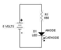
One word of caution! Never exceed the current through the LED or you will permanently damage the device. Typically the current required is between 10 and 20 milliamps. That's 0.02 amps. For 5 volt circuits a resistor between K47 (470 ohms) and 1K0 ohms will light most LED's sufficiently. I find that 10 milliamps provides sufficient illumination with the LED's specified below. With 12 to 15 volts, a resistor around 2K2 (2.2K) ohms is sufficient. Some very high efficient, high output LED's will require more current but you must consult the datasheets for those devices. Below is a circuit that will light a conventional LED.

Below is how to hookup your circuit to test the LED
There are two basic sizes of LED's T1 (3mm) and T1-3/4 (5mm). The size I use in most of my projects are the Panasonic T1 high efficiency red LED. The actual part number is from Digi-Key #P403-ND for about $0.30 in quantities of 200. Of course any LED can be used in your circuits, depending on color and output requirements.
To interface your LED to a PIC or other processor, click here.
Please contact me for any questions or problems understanding these circuits.
©2004 Rick C.