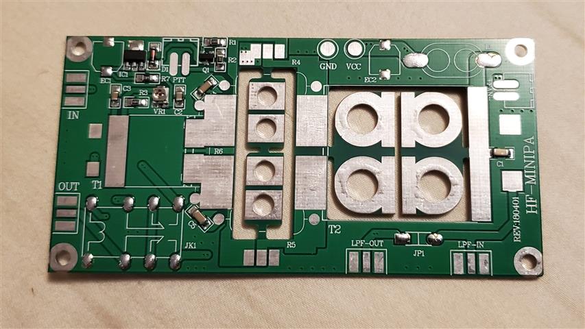
I recently purchased a Linear HF power amp called the PA70 on Ebay for around US$20.00 with free shipping from China. What could go wrong?
I received a small box with a circuit board and a handful of parts. No instructions, no links to downloadable documents, no pictures, no specifications, no nothing! Oh well, what do you expect from China? I contacted the vendor via Ebay and asked if I could be directed to documentation to assemble the unit. I got a reply to a downloadable link. Great! I downloaded the document and opened it. Well there was nothing on the two pages but two fuzzy pictures of the circuit board. I could not even identify any components.
So I did a little searching on the net for some info. I did find a few Youtube videos with some helpful hints but nowhere enough to finish the assembly. Fortunately some of the parts were already installed. Mainly the SMT components. Good! Because some posts stated even the SMT parts had to be installed. Apparently there are a few vendors selling units in different states of completion. Kit forms are easier to sell here in the US because a factory assembled unit may require type acceptance from the FCC which is very expensive and time consuming. Kits are generally exempt from type acceptance.
Fortunately there are a few schematics floating around the web. One in Chinese that didn't really help. The one that helped the most was in English and has the title "3.5--30 MHz class AB linear amplifier" Any good tech, with a schematic or pictorial could probably put this together and make it work. But in studying the design I can see some critical items missing or in the wrong place.
Looking at the schematic a number of things popped up.
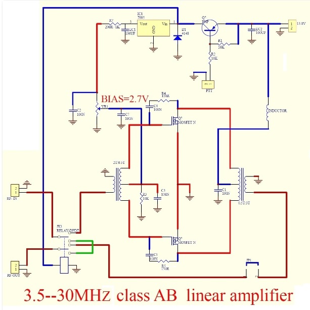
I didn't see the correct value for some bypass capacitors. The 100N (0.10uf) capacitors in some places should have been 10N (0.01uf) especially for operating in the 10 meter region. There is no snubbing diode across the relay. This will generate a good spike that will damage the 5 volt regulator and the PNP PTT transistor. The 100uf cap (EC1) should not be on the output of the regulator. Being where it is means the capacitor will backfeed voltage into the regulator output and will eventually damage it because the input voltage will drop quickly when unkeyed both through the relay current and PA load. Bad design. The only capacitor that should be on the input is a 100N capacitor to keep it from oscillating. I would also add a 100N capacitor on one side of R2, on the PTT line. Any stray RF could keep this line keyed with no RF feeding it. I noticed my kit came with 100R power resistors rather than the 150R ones shown in the schematic and in some pictures on the web. Not really a big deal. They are just there to "neutralize" or tame the output stage.
One thing that had me perplexed for awhile was the missing center tapped "coils" on the input and output pins of the power mosfets. It took me awhile to realize the "coils" are actually the stripline tracks on the circuitboard.
The circuitboard was cleverly laid out and routed to provide endholders for the ferrite cores.
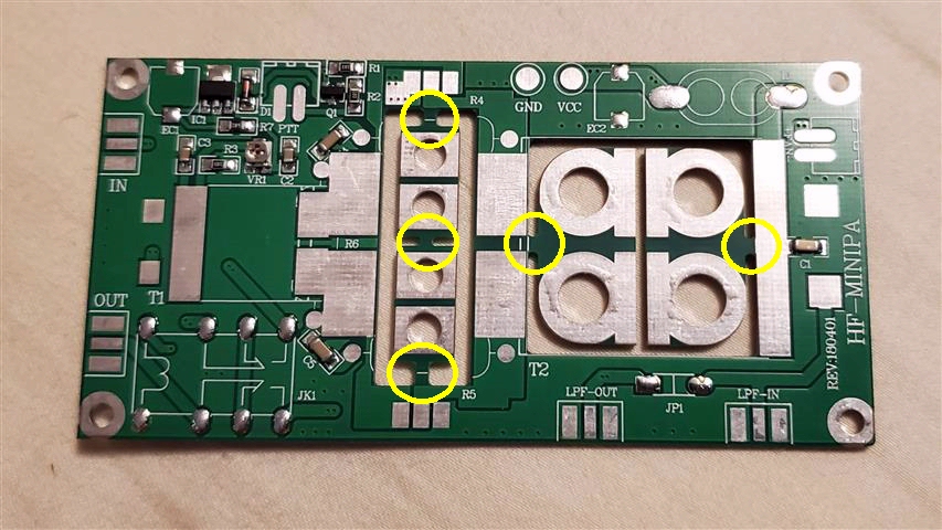
Take a side cutter and clip the five endpieces.
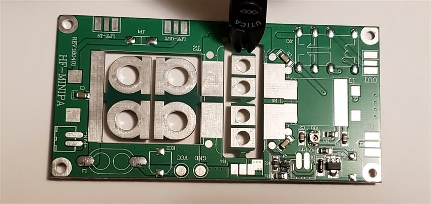
Vertically or perpendicularly solder them to the board as shown in the pictures close to the cores to hold them tight. The coil windings can be wound after the cores are mounted. So what the heck are those aluminum tubes? There is nothing explaining where they go but it looks like the go into the cores and are held in place by the vertically soldered endholders.
Bias adjustment should be made to prevent the mosfets from conducting. It should be set so when you turn the bias down, power will just start to drop and then bring it up as the power peaks. Too much bias and the mosfets will conduct and overheat.
As a broadband amplifier, caution should be taken in suppressing any 2nd and 3rd order harmonics with the insertion of a lowpass filter. The FCC requires 40db down for the 2nd order harmonic. Before operation it would be a good idea to monitor the purity of the carrier on a spectrum analyzer. You might be surprised how dirty the carrier could be. Of course, never operate the Linear amp without a sufficient load.
Two features that could be added are a sampler to sample any reflected output and fold back the power should excessive reflections occur. An RF detector to automatically switch the PA circuit on.
Copyright ©2021 by Rick C. Ver 0.1 Jan 21, 2021