The purpose of this web page is to provide information on how to build a guitar effects pedal.
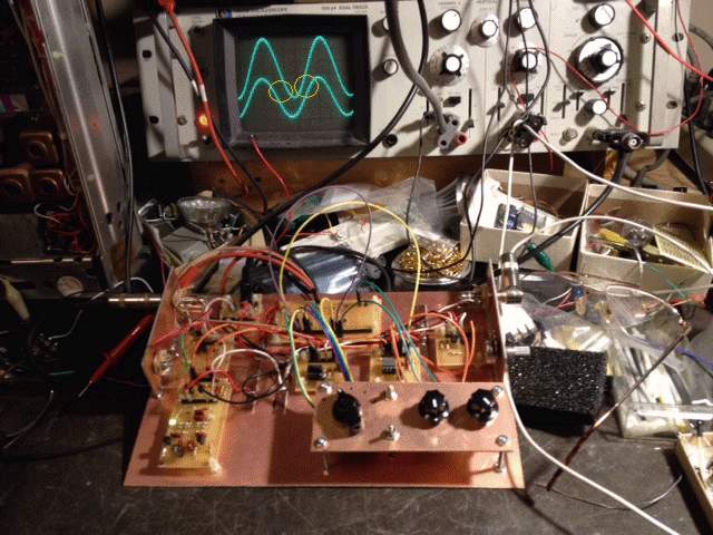
The picture shown below is what I built to test each stage and to modify each stage for optimization.
This allowed me to test different modules by just plugging and unplugging each circuit as needed.
If you are planning on building a pedal from scratch or need repair parts check out my link to Pedal Parts.
There are seven modules in the above layout. An input module, output module, tone module, effects module, diode clipping module, flip-flop module, and power supply module. There is a control/switch board to select parameters as shown on the bottom right of the picture above.
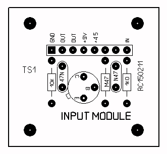
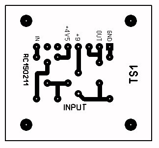
Below is the top layout and the bottom circuit of the input module:
The schematic is shown below:
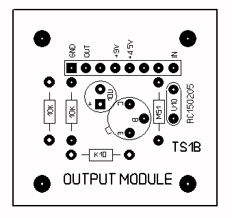
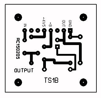
The output stage top and bottom layout are shown below:
The schematic is here:
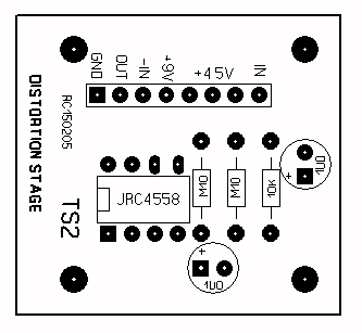
The distortion stage layout and circuitboard side are below:
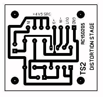
The schematic is below:
Note: The above section shows a simple diode clipping network. The diode board allows the experimenter to select any group of diodes to achieve a unique or creative sound by replacing D1 and D2 with the diode bank. There are pads to allow for MOSFET transistors, germanium, silicon, or Schottky diodes of various types and can be selected through the header and a selector switch.
The diode board is a separate board from the distortion board but the schematic contains both and is shown below:
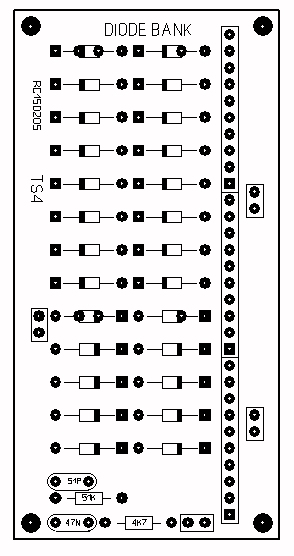

More detail will follow as to some suggested configurations.
The tone stage layout and circuit side follows below:
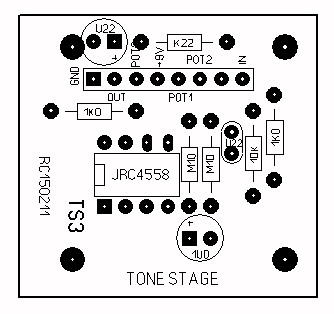
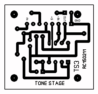
The tone schematic is shown below:
The Flip Flop footswitch layout and circuit is as follows:
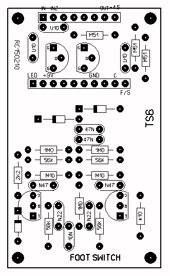
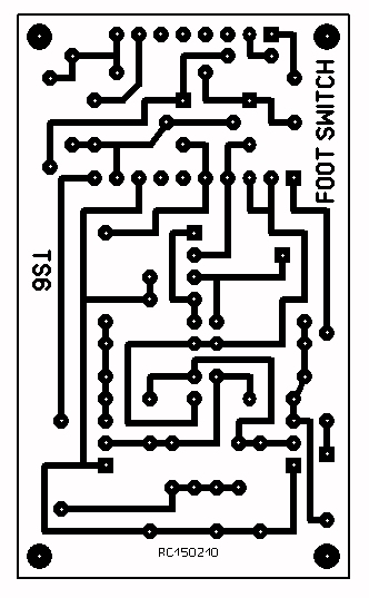
The schematic of the flipflop and audio switches are as follows:
The power supply is as follows:
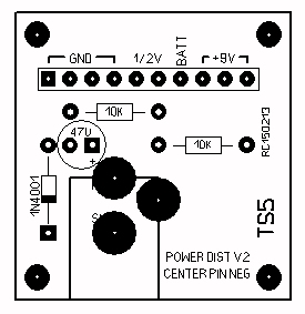
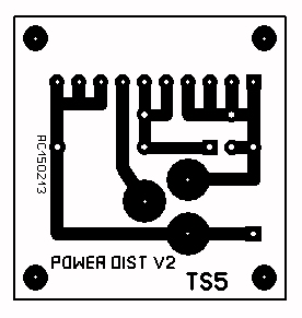
(Schematic will follow soon.)
Construction and wiring notes:
Some of the modules have a +4.5 volt source if I had a spare opamp available and some modules require +4.5 input. All connections are via header pins and jumper cables. Cables can be purchased from ebay or dx.com.
A selector switch, single pole up to 10 positions can be used to select any bank of diodes in the distortion stage.
I will be posting PDF drawings of the circuit boards so you can make you own. As time permits, I can provide you with boards for a nominal fee.
Be advised that there might be some incomplete information and I will be correcting mistakes as I find them but the overall circuit does work and if you can follow schematics carefully you can make a functioning screamer pedal.
I used surplus circuitboard material to make up the chassis. This allowed me to make changes very quickly. The boards are attached to the base plate by means of nylon standoffs.
Questions and comments can be directed to Rick C.
All pictures and text are Copyright ©2015 by Rick C. You may freely copy and quote this page as long as nothing is modified and credit is given to the website Neatcircuits.com. I would prefer you dropping me an email letting me know how you are using this info.