Proper bypassing and suppression
Updated March 27,2006 Release V1.1
For newcomers in the world of designing circuits, a subject that is often
left out or completely misunderstood is sufficient bypassing and spike suppression. When a newcomer starts to build a circuit from a schematic or
datasheet, all kinds of things can happen that cause the circuit to fail. The
first symptom is heat. The second is erratic operation.
Many designers for the ease of describing a circuit often leave out the bypass capacitors or snubbing (catch) diodes. It is often assumed that someone building
a circuit is fully versed in proper techniques in bypassing.
|
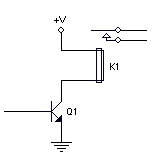
The circuit below is a theoretical
functioning circuit without suppression diode.
|
The circuit below shows the proper method
of suppressing an inductive spike.
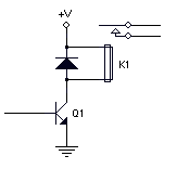
The diode should be placed physically as
close as possible to the coil to prevent
any RF noise from radiating.
|
What type of diode should you use? For small relays and
motors, a 1N4148 or 1N914 or equivalent is sufficient. For heavier applications,
a 1N4001 to 1N4004 or equivalent. They are cheap, about US$0.06 each, and lower
in large quantities.
|
This is a theoretical circuit showing the use
of a voltage regulator.
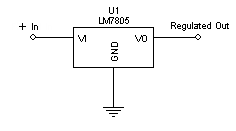
If you hook this circuit up just the way it is,
it may work, but the regulator may get hot
and shut down. |
In actuality, the capacitors keep the regulator
quiet and stable.
The capacitors should be placed physically
and electrically as close as possible
to the regulator for best results. |
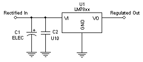
Below is a typical power supply circuit.
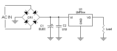
C1 should be as large, typically 470uf. The typical value is
dependent upon the load. The C2 is a U10 (0.1uf) to take any high frequency component out.
This will keep the regulator from oscillating. C1, an electrolytic can be anything from 100uf to 1000uf depending on
the load and the source frequency. A half wave rectifier will give you a frequency of 50/60 hz depending on your mains, and a full wave rectifier
frequency will be 100/120 hz. If a DC supply is used, a 47-100 uf is usually sufficient to lower the impedance of the DC source. The actual value is
not critical. The greater the value, the better the filtering. Obviously cost is a factor if designing a product that would be mass produced. In
this case you must watch the input with a scope and see if there are any deep fluctuations while exercising the load through its performance
cycle and any variations in the supply voltage.
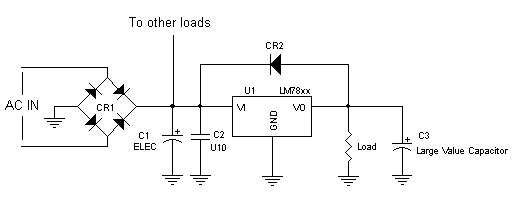
A common misconception is to place lots of capacitors on the output of the
regulator. It is not necessary to place an electrolytic on the output of the regulator
unless there are long power wires going to the load circuit. In this case, high
and low frequency bypass capacitors should be placed at or near the load circuit. Refrain from placing a
very large value capacitor on the output of the regulator. If the input to the regulator drops
below the output, damage to the regulator could occur. In the circuit below, a diode (CR2),
typically a 1N4001 or equivalent across the
regulator will prevent this from happening. This problem would
occur more often if there were other loads on the rectified side of the
regulator.
Proper bypassing is also very important for any integrated
circuit especially microprocessors, PIC's, and high speed devices. Typically a
U10 capacitor (0.1uf) must appear for frequencies under 20 mhz across the power
and ground pin as close to the device as possible. For frequencies over 50 mhz,
a U01 capacitor (0.01uf) should be used.
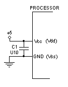
Any long lead lengths or circuit traces connecting to the device
will defeat proper bypassing. Bypass capacitors should also be scattered
liberally around a circuit board power and ground rails that is populated with
integrated circuits.
Please Rick for any questions or problems understanding these circuits.
See "Why is
my regulator overheating?
©2004 Rick C.