(Note: some schematics were hand drawn for expediting this site. They will be redrawn as time permits.)
There has been a request to propagate some of the techniques I have used throughout the years to implement simple audio switches. There are a number of complex chips out there that can accomplish this task, but many of them are expensive, hard to diagnose and troubleshoot, and single sourced. As a broadcast field engineer, troubleshooting and finding a faulty specialized audio chip and replacing it is almost impossible when in the field. Discrete components are usually stocked in a field serviceman's parts cabinet or obtained from the local parts store or even cannibalized from another piece of equipment.
The enclosed circuits have been used in many high quality, low noise applications in recording and broadcasting equipment.
Some of the requirements are: low noise, no DC pop when switching, reasonable amplitude performance, low distortion and good cutoff (muting).
The circuits shown have distortion of less than 0.1% and attenuation reaching -66 to -70 db. Some specs. may vary slightly but should come close to this.
When I refer to BP, this is the bias point which is always 1/2 the supply voltage, filtered. Keep in mind that the maximum voltage for typical CMOS is +15 volts. Staying close to 15 volts will obviously give you the most headroom although a single 5 volt supply will adequately switch line levels. Using a single supply obviously requires DC isolation with capacitors between stages and increases the parts count. Using a bipolar supply +/-5 to +/- 7.5 volts can eliminate many parts.
There are two types of audio switches that will be shown. 1) J-FET 2) CMOS switch.
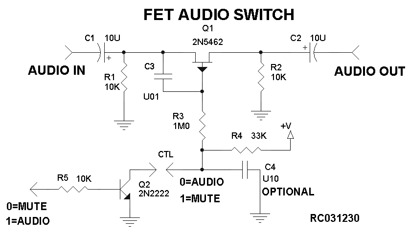
A simple J-FET switch is easy to accomplish. The use of a P-channel J-FET is required. The more common N-channel will not give the same results, especially fading. A common device is the 2N5462 or the J176 or J177 available from Jameco (part number 140142CF $.59ea or 211414CF $.29ea at 2005 prices).
The circuit below is an example of a simple audio switch:

Values are not critical so experiment for best results. The 2N2222 or any signal NPN transistor is used to invert the control logic if required. Note there is no power required except to the 33k pullup resistor. This voltage can be from +5 to +15 volts. I suggest bread boarding the circuit to insure you understand the working concept. The circuit should mute sufficiently any audio from 15 hz to 20 khz. Mute level should *easily* reach -50db. If not, you don't have the circuit wired correctly. This circuit will also fade by providing a variable voltage at the junction of the 33k and 1M0 resistors (R3 and R4). The fade will be low in distortion until -20 db has been reached. At this point some distortion will occur but by this time the signal is almost gone.
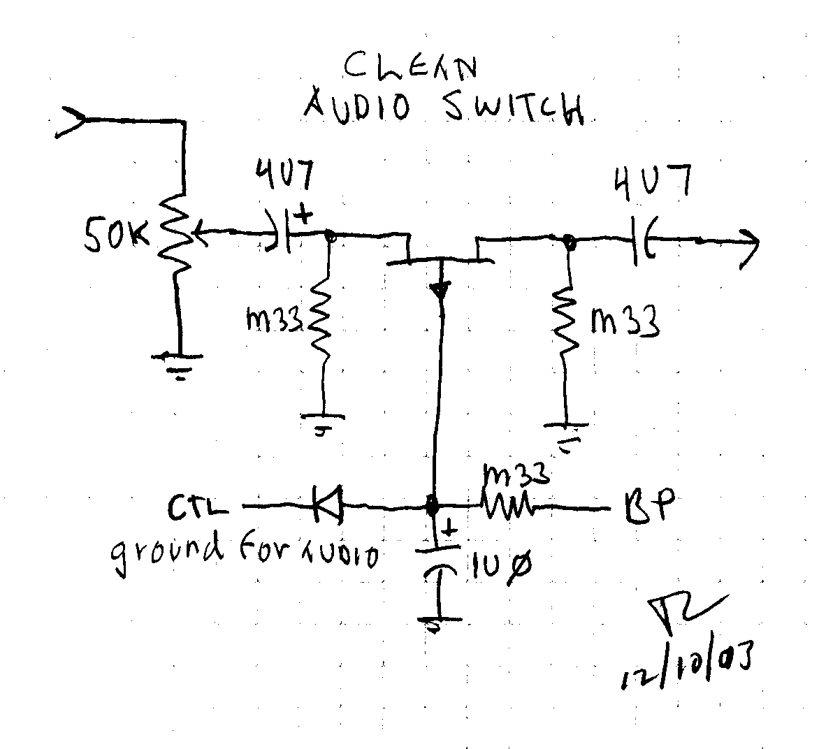
The following is another type of audio switch. Clean on/off keying
:
CMOS switches are easy to implement too. There are a few standard devices: the CD4016, CD4066, CD4051, CD4052, CD4053. The first two devices are quad bilateral switches that can pass audio or digital either direction. The 4016 can fade audio because there are no gates or buffers on the control pin. The 4066 has a buffered gate and will hard switch. The 4051, 4052, 4053 are mux bidirectional switches that can switch analog or digital, even video signals. The 4051 is a 1-of-8 switch, the 4052 is a 2-of-4 switch (great for stereo), and the 4053 is a triple 1-of-2 switch. Pinouts can be found by Google or any Motorola/Fairchild data book. A good reference to these devices is the CMOS Cookbook by Don Lancaster (H.W. Sams).
The following was taken out of an automation switcher I
designed back in 1979. The CMOS chip is the CD4016: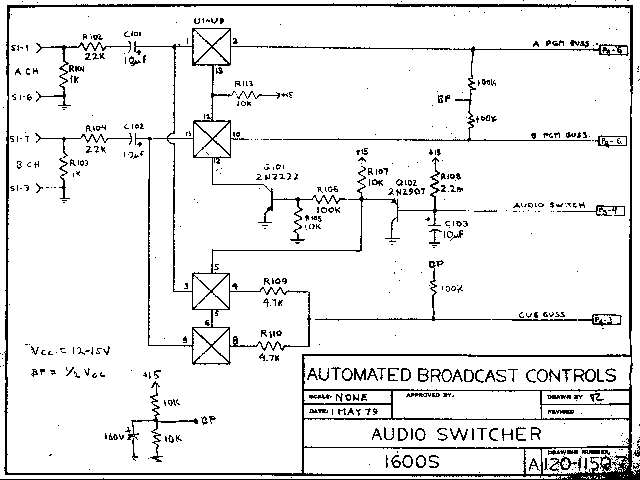
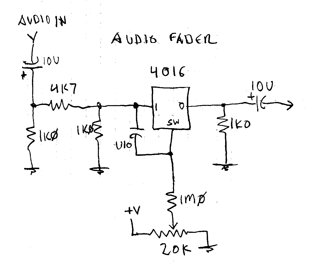
The following is a single cell switch using the CD4016:
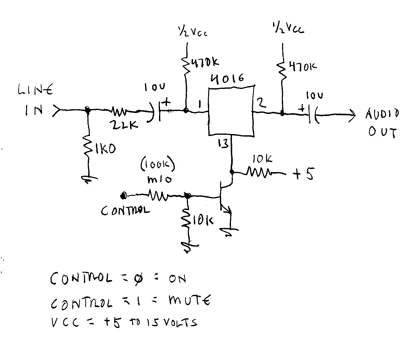
The following can be used to fade audio. A simple R/C network can be put in place of the 20k pot to fade the audio
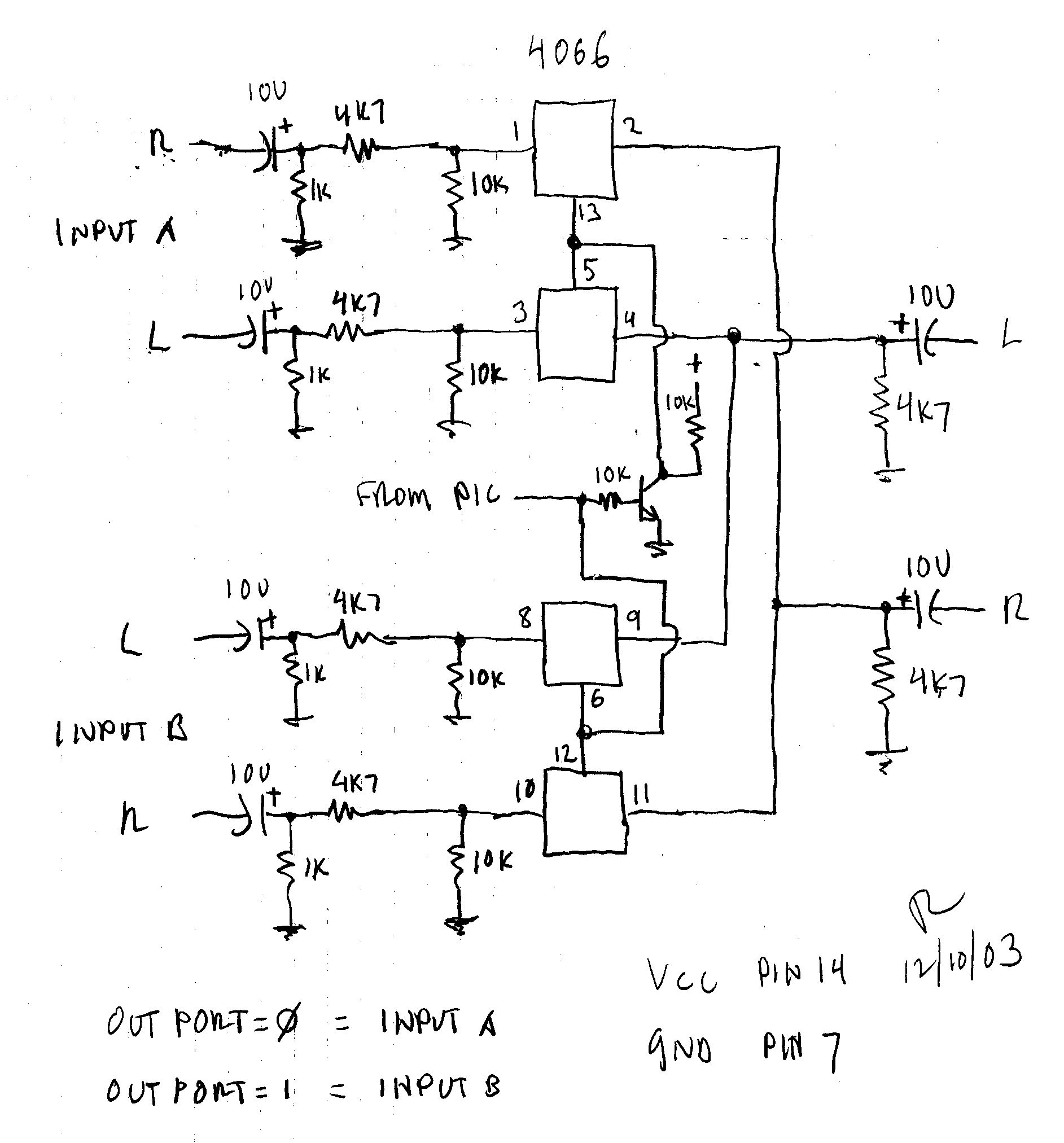
Here's a PICLIST requested circuit. A stereo A/B switch using one chip and a few parts. Note that all values are not critical but typical. They can vary greatly with little effect on performance. Just impedance and audio levels. With this circuit you could eliminate the 10k input resistors. They were originally put there to create an input match. If you have an extra output pin from the PIC and want the option of turning both channels off or on at the same time, you can eliminate the inverter transistor, two associated 10k resistors, and drive the control pins (5,13 and 6,12) separately. A "1" on the port out pin will turn the switches on. A "0" will turn everything off.
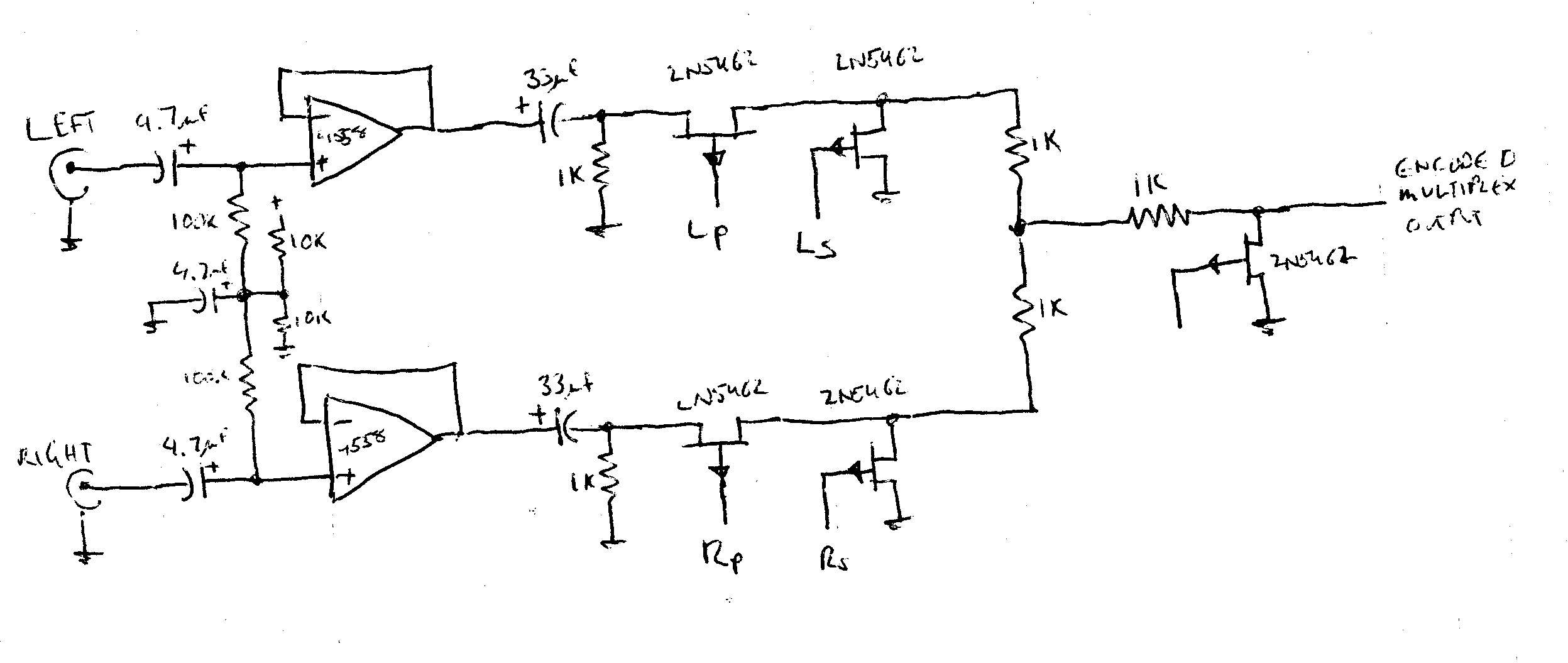
The following is part of a stereo multiplex generator circuit I helped design many years ago. It shows series and shunt switches to insure a hard, clean, audio cutoff.
As soon as I have more time, I will clean up the drawings and provide some tighter specs.
Some of the component identification I use can be referenced to this page.
This site has been providing free information for over ten years. We ask for no monetary remuneration. However the cost of keeping this domain and server running has increased substantially. If you are so inclined, you can make a donation no matter how small to keep this site always available. You can click on the Paypal button to donate. You don't need a Paypal account to contribute. Thanks for your support.