High Voltage Warning: Caution must me taken when working around the switching supply when powered up. Lethal voltages are present in the primary circuit. Even when powered down the main filter capacitor has potentially dangerous voltages and should be properly discharged before working on it. When power is removed, voltage on the primary filter capacitor should be bled off via a resistor rather than just shorting the capacitor which can damage it.
Switch Mode Power Supplies (SMPS) have always been a mystery for most of us. It is a very efficient "transformerless" power supply that can provide a stable source of DC voltage or voltages.
Switching supplies are used in almost all modern electronic equipment including computers, monitors, TV's VCR's satellite receivers and more recently made wall warts.
Since there is no bulky linear power transformer they are relatively light weight.
Because of its inherent design, it is sensitive to heat, moisture, surges and spikes. There is some minor switching noise between 60 and 100 kilohertz too. I have had many switching supplies fail and repairing them for most of us is almost impossible.
Since they are relatively cheap most just replace them and toss the defective ones. I have tinkered with many, with very little success. I must have hundreds of them in storage. I usually scrap the wire, connectors or other parts for other projects. Most of them probably have just a 2 cent part that has gone bad that renders the whole power supply useless.
Repairing these supplies can be very difficult and dangerous if you don't take special precautions when working around the 170 volt line voltage present in the primary circuit.
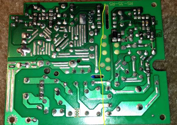
Upon observing the bottom of the circuit board you can usually see a distinct segregated section of the primary and secondary. This keeps the primary high voltage away from the low voltage circuit.
Many supplies have multiple outputs. Some sense the voltage of each supply and are part of the feedback circuit. Not only for voltage regulation but to stall the supply if one of the outputs becomes shorted or exceeds desired voltage. Some supplies need a load in order to function properly and will not start if no load is present.
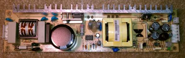
Failures can be attributed to a blown fuse, overheating, open or shorted high voltage capacitor, shorted rectifier, defective MOSFET switching transistor, burned resistors, and defective components in the feedback circuit. In recent years many cheap Chinese capacitors have failed by exploding or leaking. These can be detected easily by looking for a bulge in the aluminum on the top of the capacitor. But just because a fuse is blown or a resistor is burned doesn't mean that is the only bad part. One has to determine why the resistor or other component failed.
Much can be learned by studying the simplified circuit below. This excerpt came from the datasheet for the NCP1203 which is a typical component in most switchers and can be downloaded here. The 1203 belongs to the NCP1200 family of PWM current mode controllers.
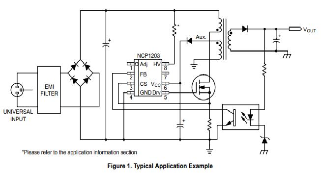
Here's where the critical part takes place: A sample of the output voltage will appear on the optoisolator and it will slightly turn on when the zener in the circuit starts to conduct. As the output of the optoisolator starts to turn on it pulls pin 2 of the 1203 down to reduce the pulse with and thus the drive to the transformer via the MOSFET. When this happens the output voltage drops ever so slightly and the optoisolator starts to release. This completes the quick and tight feedback loop and the voltage remains fairly constant over wide load conditions. The 1203 generates wider or narrower pulses to the MOSFET which in turn keeps the output voltage constant as seen on TP2 images below.
What is happening here is that the optoisolator is actually operating in its linear region and not turning on and off hard as one would assume. This can be seen in the LPS-75-24 circuit below.
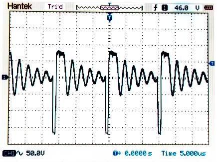
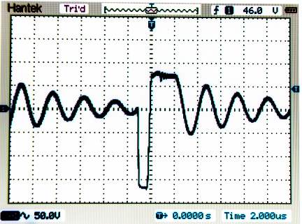
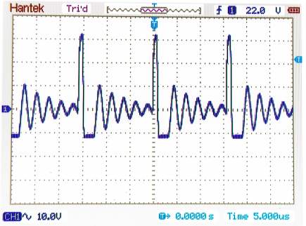
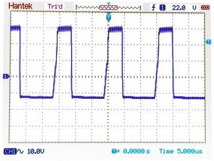
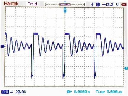
Above is TP3, the drain of the MOSFET. Second frame is expanded for more detail
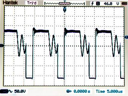
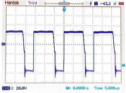
Above is TP3 under half load and under full load. Notice the top of the waveform is wider under full load.
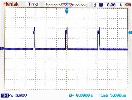
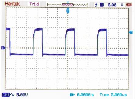
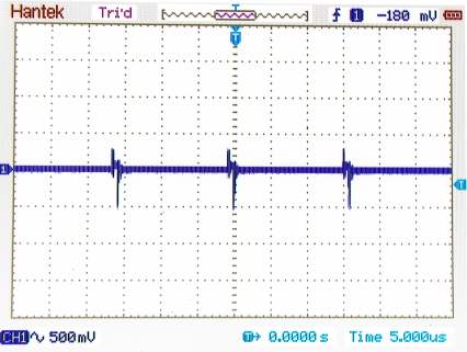
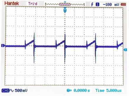
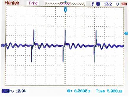
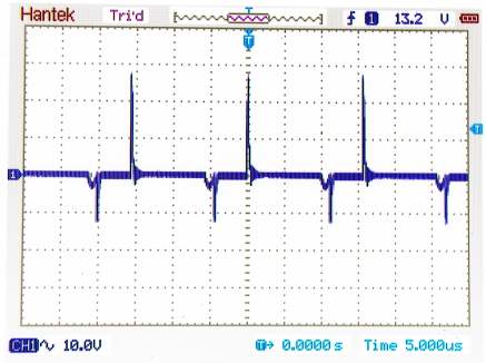
Above is TP2, the output of the 1203 switching chip under no load and half amp load.
.
The first circuit below is the hot (primary) side of the Meanwell LPS-75-24 24 volt 3.2 amp power supply
The circuit below is the secondary side of the Meanwell LPS-75-24 power supply
In the center of the schematic above you will see the over voltage protection and external shutdown input. ZD52 is a 30 volt zener which will remain dormant as long as the output voltage is within specifications. Also a positive voltage on the inhibit input will turn on optoisolator ISO2 and stall the 1203 switching device. Should the voltage exceed the ZD52 threshold, the gate of SCR1 will cause the SCR to conduct and shut down the 1203 switching device.
The circuit to the right of the over voltage protection circuit is the regulator circuit in the feedback path. R57 sets the output voltage by adjusting the shunt regulator SHR1 whose cathode sits at around 9.1 volts for a 24.0 volt output. ZD51 and associated resistors keep the optoisolator ISO1 just at partial conduction. If the voltage "starts" to drop the optoisolator starts to shut off and the 1203 switcher pushes the pulse width wider to provide more drive to the output. As the voltage comes into spec., the optoisolator starts to turn on and tells the 1203 switcher to hold its pulse width. This makes up the closed loop feedback and keeps the voltage fairly constant.
R52 provides a suitable dead load to keep the output from running away and the power circuit from shutting down.
One simple way to troubleshoot a supply like this is to place 24 to 40 volts or so across the bridge rectifier or main filter capacitor without any high voltage AC from the line input. The supply should function normally with little or partial load.
Important note: This is just one simple switching supply. Most supplies are much more complicated with many more components and circuitry. As an example, the supply shown above is a current model. It replaces a supply in a piece of equipment designed in 1995. The supply in that model had twice as many components on the top and bottom of the board. Since technology has improved and components have gotten better the part count has decreased.
The picture below is the Meanwell LPS-75-24 power supply available from Jameco
Electronics
for $23.95 part number 244727.
This and all other pages on this website are Copyright ©2014 Rick C.
This site has been providing free information for over ten years. We ask for no monetary remuneration. However the cost of keeping this domain and server running has increased substantially. If you are so inclined, you can make a donation no matter how small to keep this site always available. You can click on the Paypal button to donate. You don't need a Paypal account to contribute. Thanks for your support.