Copyright ©2014 Rick C. Ver 1.3 May 31, 2014
Ver 1.4 Updated Jan 14, 2023
In recent years there has been a conversion of speaker connectors from binding posts and/or 1/4 inch jacks on the power amplifier to Speakon connectors designed by Neutrik of Germany. In parts of the EU, the binding posts have been discontinued by law. There have been problems with accidental reversal causing an out of phase condition or grounding of the output of amplifiers if the black binding post is grounded on the speaker side, to connectors popping out during use. Almost all new speaker cabinets use Speakon connectors now. Some amplifiers will accept Speakon and 1/4 inch plugs in the center of the Speakon jack.
Neutrik pioneered the development of reliable, high quality twist-lock connectors which are fool proof and water proof. Beware of some lower cost eBay connectors which are Chinese spin-offs of the German made connectors. The cheaper ones are not as durable and will fall apart during normal use. I recommend purchasing them from Markertek.com. Search for NLT4MP. Currently US$5.29 in single quantities as of Oct 2010. If you are going to make your own cables, search for MLT4MX which are about US$7.59 in single quantities. I recommend using good quality 12 gauge rubber or vinyl cable such as 12-2 SO or 12-2 SOJ. Even though there are three conductors, just use the black and white wired to 1+ to 1+ and 1- to 1- and cut the green off. For making a bridge cable, the end on the amplifier should be 1+ and 2+. Make sure you properly mark the bridge end and configure your amplifier for bridge mode. I use a piece of red heat shrink tubing on the bridge amplifier end of the cable and also mark with a Sharpie™ that it is a bridge end. Otherwise you will permanently damage the amplifier. For a more detailed description and instructions for hookup, go to the Neutrik site. Also you can download a PDF here that explains a lot about connecting and using Speakon's. Wiki also has a good description.
There's also a bit of confusion as to which is the male and which is the female end. An easy way is to look at the index pin in the very center of the connector. If it has a hole in the center it is a MALE. If it has a solid pin in the center, it is a FEMALE.
As a general rule, the male connectors are on the amplifiers and speakers, and the females on both ends of the cable. To extend a cable one can purchase a double male connector/adapter from Markertek to daisy chain two female cables.
I personally had problems with 1/4 inch plugs literally popping out of the speakers during loud low frequency passages. We had to gaff tape the cable to the back of the cabinets to keep them operating.
As a bonus I have decided to release my personal copy of the actual wiring of the legacy Bose 802 enclosure cabinet. Please email request for the PDF from the link at the bottom. If you happen to mix up the wiring when replacing or replacing the surrounds, you will never get it exactly right.
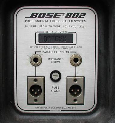
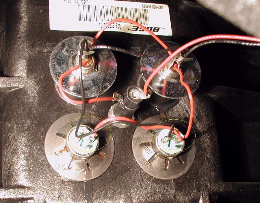
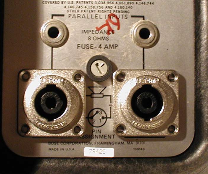
The early Bose 802 original series (~1970) and Series II had two 1/4 inch and two XLR male connectors wired in parallel on the back of the cabinets as shown below.
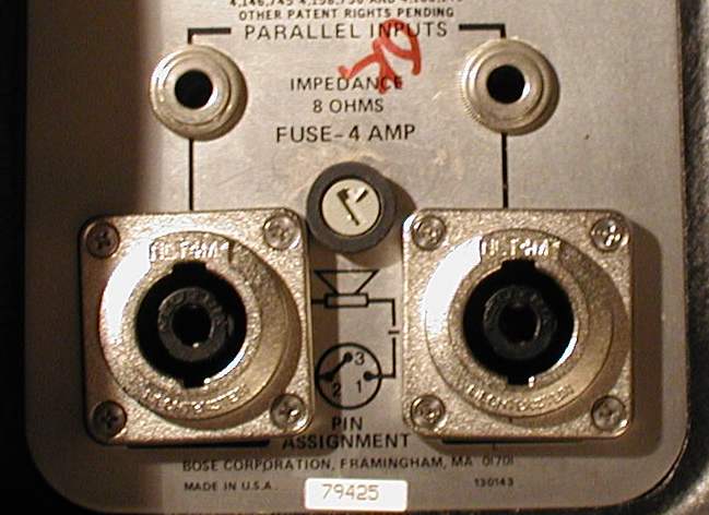
These instructions will take you through the process of replacing the XLR's with Speakon's as shown below:
There are going to be some special tools needed to make the conversion as quickly and cleanly as possible. These are:
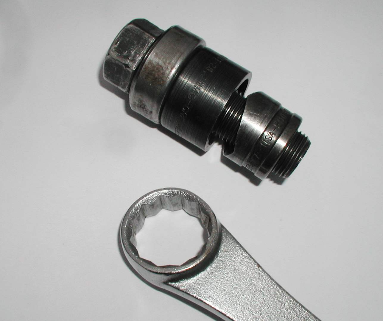
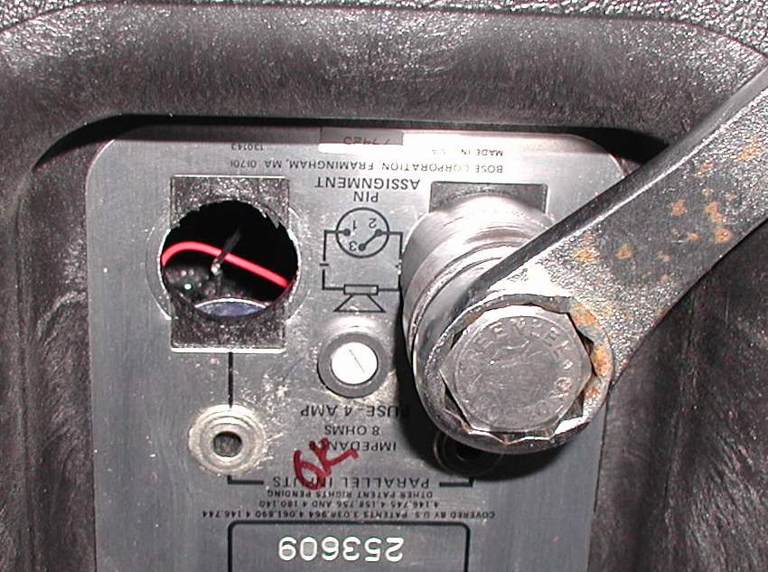
3/4 inch Greenlee (actual 1-1/8") chassis punch available from most fully stocked hardware or electrical supply house. This hole punch requires a 1 inch wrench to operate the punch. The punch leaves a clean perfectly round hole in the back of the enclosure.
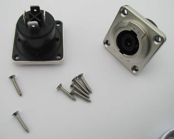
Actual parts needed are two Neutrik NLT4M connectors, eight #4 X 3/4" stainless steel wood screws as shown below.
Also four solderless spade lug connectors and two pieces of 16 ga. stranded wire about four inches long.
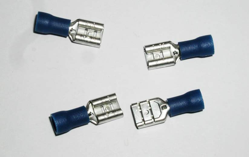
These are .250 female tab, 16-14 awg available from auto parts stores or most hardware
stores
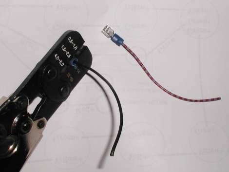
They can be prepared ahead of time and are shown below. Buy or borrow a good solderless crimper because a vibration proof secure connection will result in reliable operations.
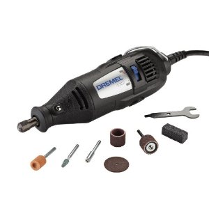
Also a battery operated reversing drill with clutch, and a Dremel tool with a flat cutting blade (flat disk shown below in center) is required.
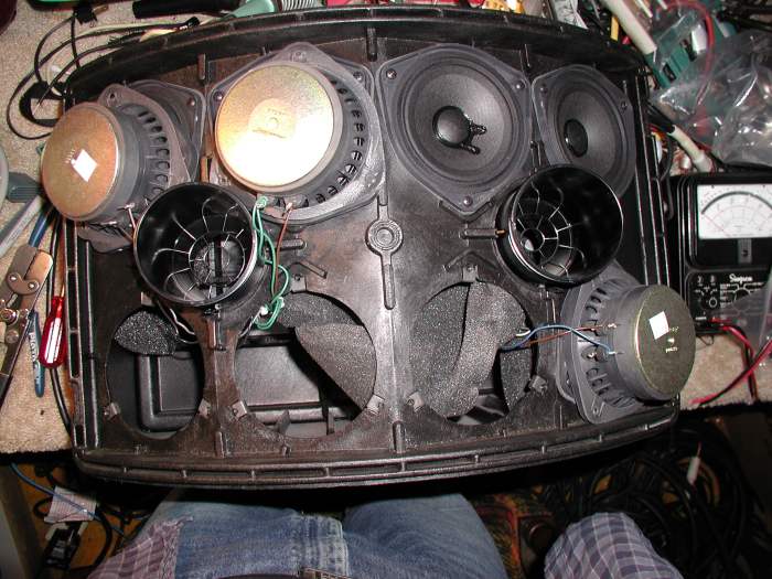
Step #1 - Remove the two port rings and Bose logo bezel. Remove the grille. Set the enclosure on a work surface with the bottom (mounting base) toward you as shown.
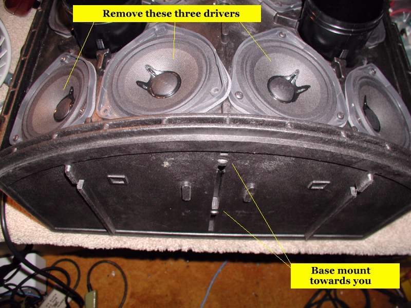
Remove the three screws from three drivers closest to you from left to right. Carefully remove the drivers. You may have to carefully pry the drivers off the enclosure because there is a gasket sealing the driver to the enclosure. Keep these intact because these need to make an air tight fitting when replaced. Be careful not to puncture or tear the driver cones.
The wires to the drivers will seem short but this is because the wires were twisted tightly to keep from vibrating loose during use and transportation. In the Series II versions there is a foam blanket just behind the drivers and the wires are twisted behind the foam. In the earlier series there are fiberglass bats strategically placed inside the enclosure. You might need to make a cut in the foam to gain access to the inside rear of the enclosure as shown below.
You might want to make note of the wire colors on each driver in case you accidentally pull one loose. One misplaced wire and the speaker will not operate. As shown above, carefully roll the foam back to expose the inside connectors as shown below.
As you can see above, the two XLR connectors are held in place with retaining clips and sometimes glue. With a pair of wire cutters cut all the wires off the XLR connectors and remove any loose wires. This should leave only one red and one black wire loose. With a pair of wire strippers strip back about 3/8 inch of insulation on both wires and position them out of the way for now.
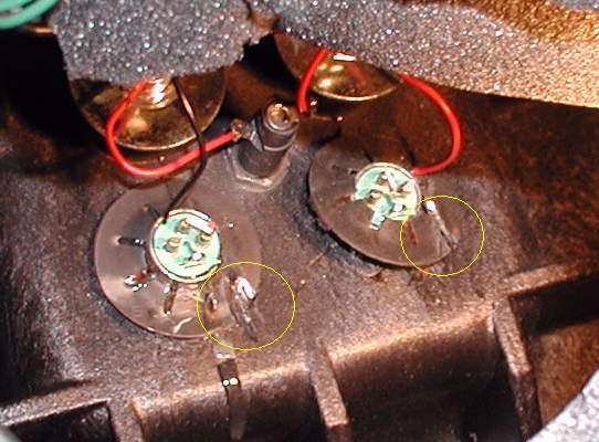
At this time you will need to take a Dremel tool with a thin cutting wheel and place a cut on each retaining clip at the thinnest point on the retaining clip as shown below.
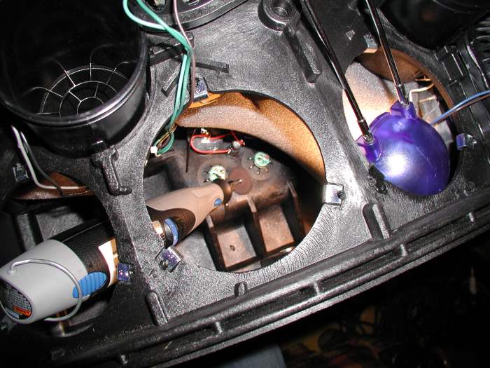
Above shows a small blue desk light to see inside the enclosure.
Below shows the two cuts made by the cutting tool.
Carefully cut the clips. Then use a small screwdriver to pry the clips off and discard. Take a long screwdriver or long steel punch and tap the two XLR connectors out. Clean up any debris left behind. A view of the connectors punched out is shown below.
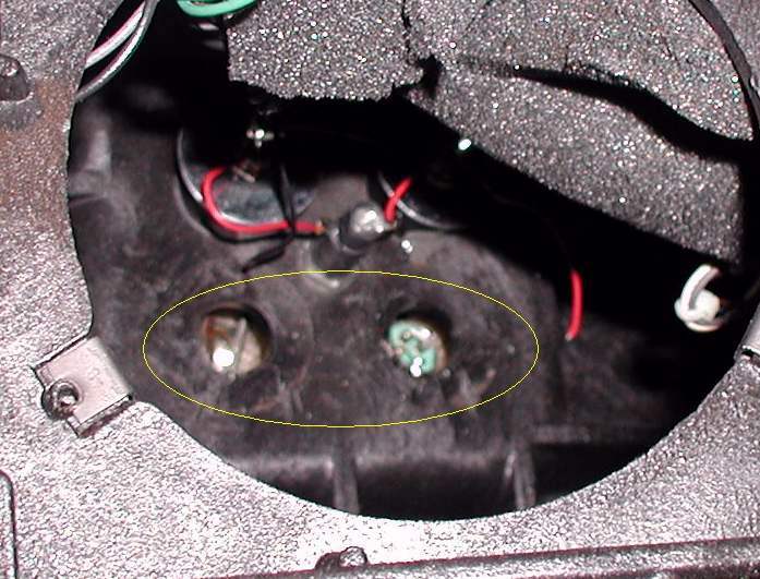
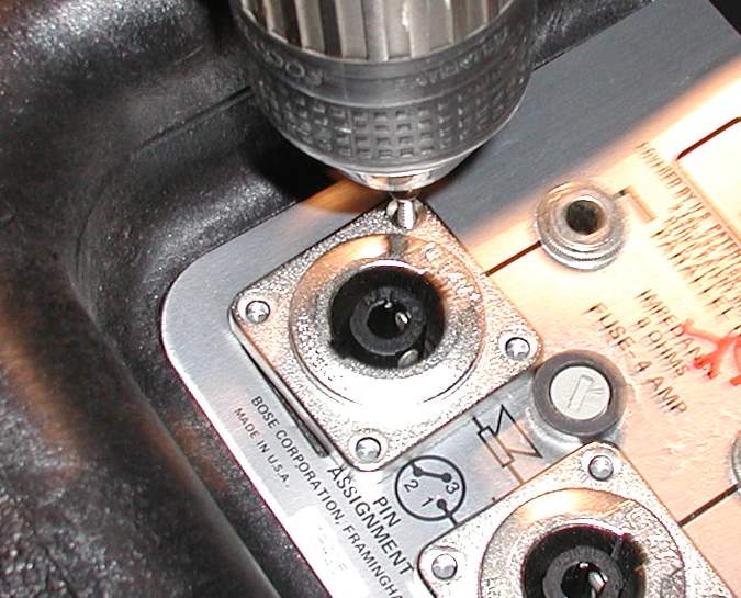
Be extra careful not to punch a hole in the driver paper cones or let them drop down as you turn the enclosure up side down and drivers facing away from you on the bench. With the chassis punch enlarge the two holes on the back of the enclosure as shown below.
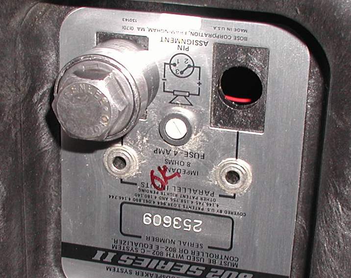
Above, the right hole is the original size.
Above the left hole is the widened size. If there are any jagged edges on the foil plate from the hole cutting, tap them flat with a hammer or other tool. Be careful when disassembling the tool to remove the plastic spoil. Don't damage the punch by hammering on it. Set the enclosure upright with the drivers up and install the drivers with just one screw to keep them in place.
Prepare the Neutrik connectors by clipping off the four little plastic tabs behind the metal flanges. This will allow the connectors to lay flat on the back of the enclosure as shown below.
With an electric drill and screws, carefully align the connectors and mount
the connectors as shown below.
Try to keep them square to make them look good as shown below.
As you can see above, the connector on the left is slightly out of square but not too objectionable.
Once connectors are secure, invert the enclosure and remove the drivers carefully positioning them away. Here is where it gets pretty tight and requires some patience. After preparing the spade lugs and wires as shown in a previous image, carefully strip about 3/8 inch insulation from the other end of the wires. Carefully working INSIDE the enclosure, crimp the two black wires to another spade lug. Do the same with the red wire. Tug on them to make sure they are crimped securely. If one comes off, start again with a new spade lug. When done it should look like the image below.
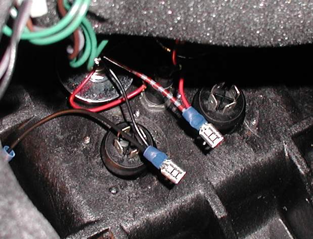
The back of the Neutrik connectors are marked 1+, 1-, 2+, 2-
You will need to connect the black wires to the 1- and the red wire to the 1+ on both connectors as shown below.
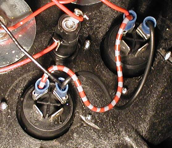
Make sure the spade lugs are pushed all the way down till they
snap in. A dab of clear silicone caulk (RTV) around the lugs will insure they
don't pop out.
This concludes the wiring. Now carefully position the foam so it sits just behind the drivers when they are mounted. Carefully mount the drivers making sure the wires are twisted together so as not to vibrate. Do not over tighten the three screws on each driver. Just firm enough to make a tight seal. Install the grille, the bezel and port rings.
This completes the process of the conversion.
If this was helpful to you, please drop me an email and let me know of your success.
©Rick C. 2023
This site has been providing free information for over ten years. We ask for no monetary remuneration. However the cost of keeping this domain and server running has increased substantially. If you are so inclined, you can make a donation no matter how small to keep this site always available. You can click on the Paypal button to donate. You don't need a Paypal account to contribute. Thanks for your support.